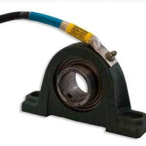
Tempscan Heat Sensor Switch Model CD/HX-SS
Bulletin 100.031
- Belt Sideslip Switch
- Surface Over-temperature Detection
Description
Bulletin 100.031
- Belt Sideslip Switch
- Surface Over-temperature Detection
The CD/HX-SS contains a reed switch operated temperature switch which functions by the following two principles:
- A reed switch actuation occurs because of changes in strength of magnetic field in the vicinity of the contact gap within the unit.
- Certain materials within the switch exhibit great changes in magnetic reluctance when the temperature is varied in the vicinity of the materials Curie point or Curie temperature: Temperature in which a magnetic materials’ ability to conduct magnetic flux is severely reduced.
Therefore, when the heat applied to the device exceeds its designed set-point, the magnets in the switch lose their ability to “hold” the reed switch in the normal state.
When a moving belt rubs against the sensing surface, the temperature rises causing the internal switch to activate.
Specifications
- Switch Enclosure: Cast Brass, Copper Alloy 865 Manganese Bronze.
- Temperature Set-point: Nominally 45ºC, (113ºF)
- Contact Arrangement: SPST Form A (N.O.) or Form B (N.C.)
- Maximum Voltage: 24VDC/120VAC Maximum Power: 12VA
- Maximum Current: 0.5A
- Tolerance: ± 5ºC
- Temperature Set-points Available: 0-115ºC in increments of 5ºC
Installation
Caution
After an alarm condition, check functioning of the internal switch by confirming its operating temperature (see label for operating temperature). Place unit in upright position, immerse to mid-point in hot water at least 10ºC (18ºF) higher than indicated operating temperature.
Additional information
| Switch Enclosure | Cast Brass, Copper Alloy 865 Manganese Bronze |
|---|---|
| Temperature Set-point | Nominally 45ºC, (113ºF) |
| Contact Arrangement | SPST Form A (N.O.) or Form B (N.C.) |
| Maximum Voltage | 24VDC/120VAC |
| Maximum Power | 12VA |
| Maximum Current | 0.5A |
| Tolerance | ± 5ºC |
| Temperature Set-points Available | 0-115ºC in increments of 5ºC |